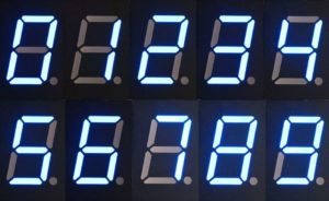
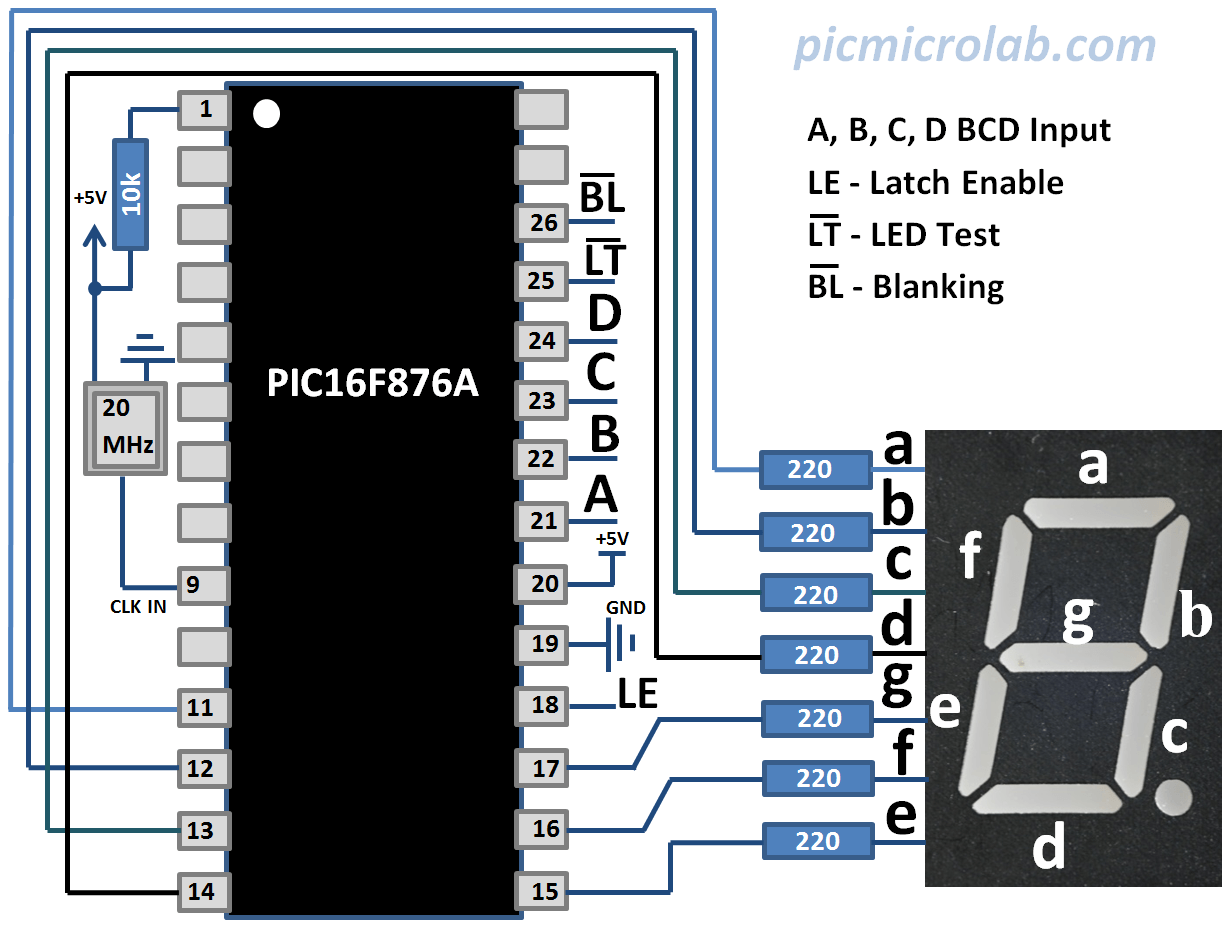
In this post I’ll show how you can drive 7 Segment LED display with PIC16F876A. Instead of using a dedicated IC’s like 4511 we’ll program the micro controller to convert BCD input code 0 – 9 to a 7 Segment LED display code. PIC16F876A can sink enough current to drive a standard common anode display without external current boosting transistors thus simplifying the design. Decoder has 4 BCD inputs in addition to Latch (LE),LED Test inverted (LT) and Blanking inverted (BL) pins. LED test and Blanking inputs allow to test, turn the segments OFF and if necessary to multiplex several 7 segments.Also you can Latch the inputs by applying “1” to LE pin. BCD code is identical to a binary representation up to 9 therefore requiring 4 bits for each digit. Decoder will ignore higher value inputs. In order to show additional characters you’ll need to modify the code, essentially building a binary to 7-Segment converter. Schematic and source code are available on the next page. Here you can see all implemented digits.

Segments a-g are connected to PORTC of the MCU. If you are going to build this circuit pay attention to how they are connected to controller. PICkit3 programmer was used to download the code but I did not want to overload the schematic with too much information.You can see how to connect it at this link.

Source code and a compiled HEX file can be downloaded here.This code should also work on PIC16F877/887 however I did not test it on these devices.You’ll need to change the Include file name and rebuild the project.
