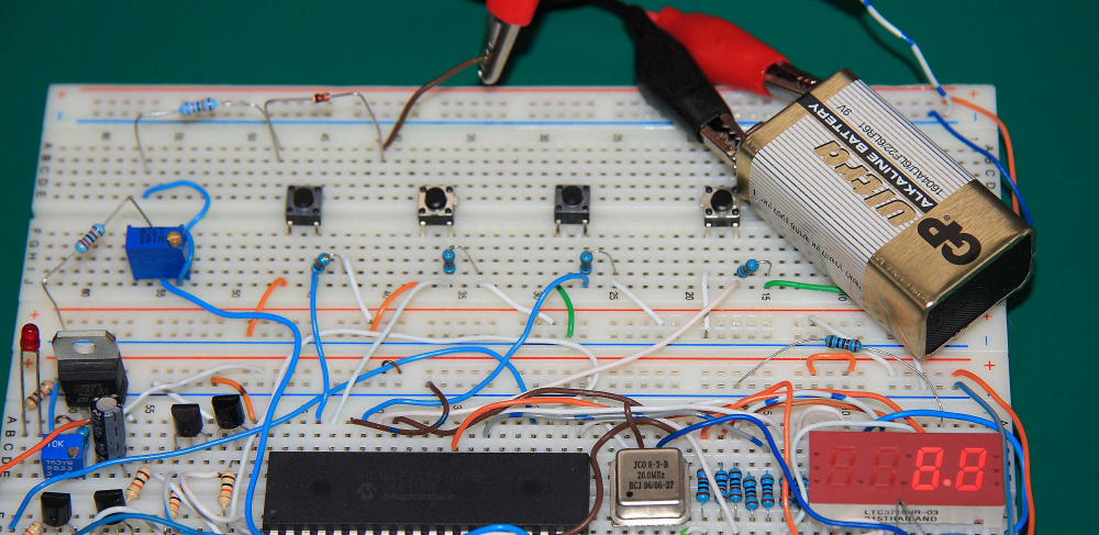
Simple digital voltmeter can be built by using PIC microcontroller and a few discrete components. PIC16F877A 10 bit ADC module was used for this purpose, we’ll work only with 8 upper bits to translate input voltage to digital form and send it to LED display. Hardware of this design is very similar to digital clock project hardware (minimal changes required). Only SW4 was implemented for display test. SW 3, 2,1 still in the schematic but were not used for DVM.
Analog voltage is connected to AN1 (Pin 3) through simple voltage divider for 1:10 attenuation. With 8 bits of data the Max reading after ADC will be 255 – all bits are “1”.In order to display the result this number should be separated into individual digits: 100’s,10’s,1’s – this is done by subtracting 100’s from the result and incrementing the 100’s counter. Next we move to 10’s and 1’s.Hex and assembly files can be downloaded at the bottom of the page. The only adjustment needed is for R1.Aplly 5 V DC to voltage divider input and tune R1 till you get 0.5 V in analog input (Pin 3).LTC3710HR data sheet can be found here. If LTC3710HR
Same battery was measured with UNI-T UT71D

