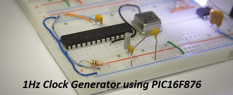
In this article we’ll see how to generate 1 Hz clock with PIC16F876/877 PIC microcontrollers. 3 different approaches will be demonstrated. The most basic solution is to use nested loops to “waste” enough instruction cycle time in order to produce 1 sec delay. The main advantage of this implementation is its simplicity.No additional external hardware is required, just a simple nested loop that decrements the register value till it reaches zero , then reload second register and repeat. Here is the code. More precise timing can be obtained by using Timer1 with external 32.768 kHz oscillator. The accuracy is achieved by using a crystal and the fact that its frequency can be divided by a power of 2. This implementation is also more efficient than nested loops as it uses an interrupt generated by Timer1 each time it overflows.The formula for time delay in current configuration is given by Td = 1 / 2^15 * ( 2^16 – TMR1H:TMR1L) * Prescaler value. See exact settings in assembly source code. In the next figure you can see a schematic of this design. PIC Programmer connection are not shown.
LED connected to RC2 will be turned ON/OFF for 1 sec – actually 0.5 Hz, change Timer1 initial values to produce 1 Hz signal. Another approach is to use RTC – Real Time Clock IC to extract a required time interval. I’ve already described how to interface 2 of these devices in PCF8573P I2C Real Time Clock and Digital Stopwatch posts. You are invited to review these articles for more detailed information.

