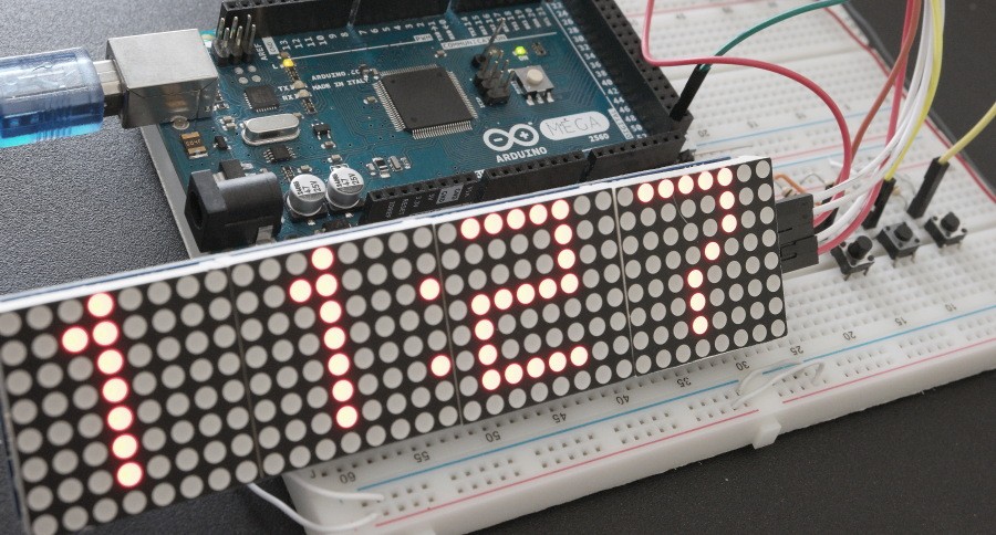
Here is another digital clock design based on Arduino platform. This time it uses 4-Digit LED Dot Matrix module to show the time. Similar design with LCD display is available here. The Dot Matrix module consists of four MAX7219 chips connected in serial and 8×8 Dot Matrix Displays. I’ve used Arduino LedControl.h library to communicate with display module. This library contains the basic function required for controlling the display. For example you can initialize the MAX7219 IC, set display brightness, turn ON/OFF selected matrix columns and rows. See how to connect the display module to Arduino MEGA
By sequentially updating the rows you can create a desired character set like it’s done in attached basic Arduino sketch. The code is basically built around 3 depended counters for settings and adjusting the time – hours and minutes. I’ve also included a picture of a prototype board used to develop the clock design. External 10k pull-up resistor connected to the push buttons can be omitted as ATmega2560 chip has internal pull up enabled by pinMode(TimeSet, INPUT_PULLUP). A more advanced paid version of the clock code is available at this link. It uses timer interrupt to provide much better stability and more precise timing.
In order to set the time you need to press together Time Set button and Hour or Minutes as shown in a short video next. Alarm function is not implemented in current design but can be easily added to the code. You just need to add another set of counters for Alarm and compare the Time and Alarm variables. If they match sound the alarm with simple 5v buzzer.

