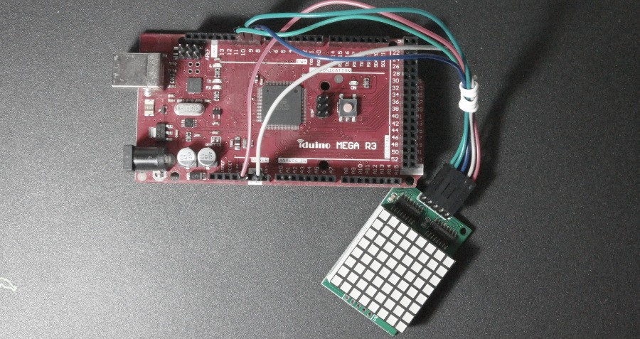
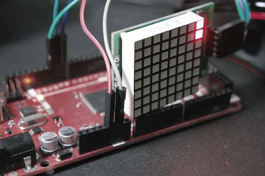
8×8 LED Matrix chaser based on Arduino MEGA compatible board will be presented in this post. It uses a LED dot matrix display module
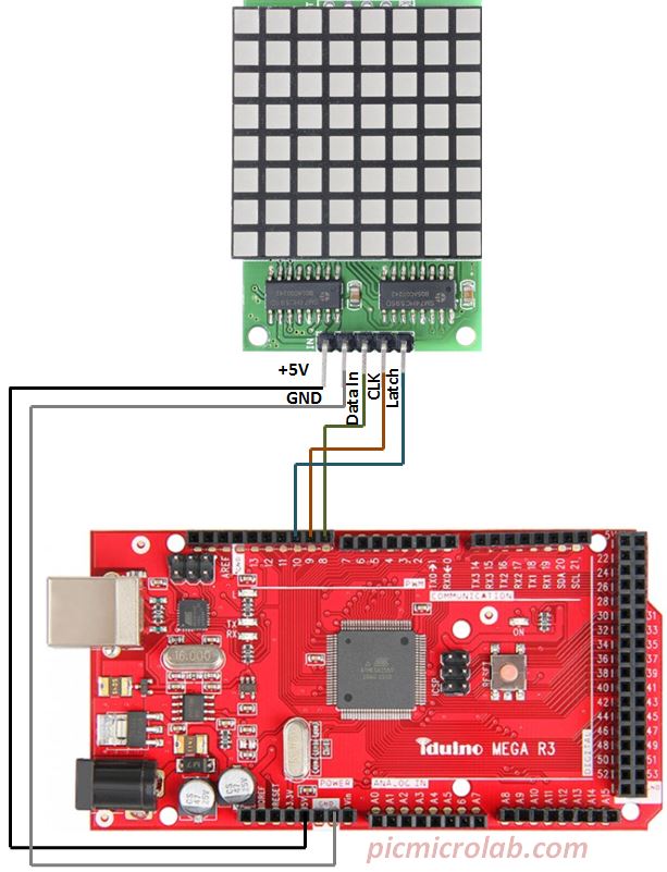
with two 74HC595 shift register chips connected in serial to control the LED output. Similar design based on MAX7219 LED driver can be found here. For this project only 3 additional I/O lines except VDD & GND are needed. These are Data In, Clock and Latch lines. Circuit schematic diagram is shown in the next figure.

The interface code in the attached Arduino sketch sends 2 byte of data representing the rows and columns to be driven in order to create a desired pattern on the LEDs. Currently only one LED pattern is implemented as can be seen in the short video on the bottom of the page. Additional LED patterns can be easily added. For more details see Arduino code here.

