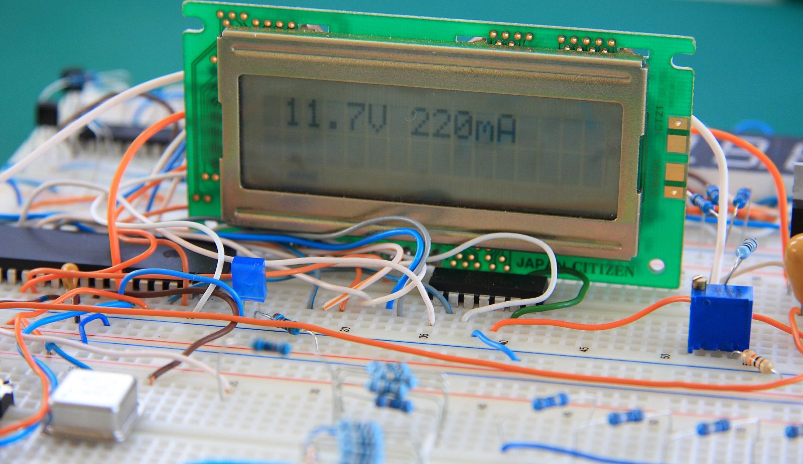
Power Supply is probably the most common electronics project you can build.This is a basic design for digital power supply. It was built around 3 main components. Digital potentiometer – MCP4251-502E/P, Low Dropout Voltage Regulator – MIC29152
and PIC16F877A
.The idea behind it is simple. Take a standard LDO design – 2 resistors, first resistor between ADJ pin and Out, second resistor between ADJ and ground and modify it to include digitally controlled resistor in the desired range. Now PIC can control the resistor value by sending SPI commands/data thus changing the output voltage. For this project MCP4251-502E/P
was used. It’s a dual 5kOhm Potentiometer with SPI interface. Special attention should be put on verifying that digital potentiometer is operating within its Max operational rating. For MCP4251 the current through resistor network should not exceed 2.5mA and voltage on resistor terminals at 5v Max. Full datasheet can be downloaded here.Few words about LDO.MIC29152 is a Low – Dropout Voltage Regulator with overcurrent and over temperature features built in and its 5 pin version has Enable input that can be controlled by PIC microcontroller. Enable pin was used to shut down the regulator if Max allowed current is reached. Although MIC29152
can handle 1.5A the Max current in this version was limited to 400mA.For higher currents a bigger Heat Sink
should be used and current sensing function will require some changes. Due to greater heat dissipation higher power rating resistors should also be used. This design was built and tested only up to 400mA.For proper operation 2 independent power supplies are needed. One for PIC power, second for 14-16 V Input to LDO. If PIC is supplied from the same power source as LDO for example by 7805
or LM317
current limiting function will not work correctly and LDO
will not be shut down at desired current. Instead in case of a short at the LDO output PIC will stop operating leading to MIC29152 overheating till its over current/over temperature protection will shut it down.
