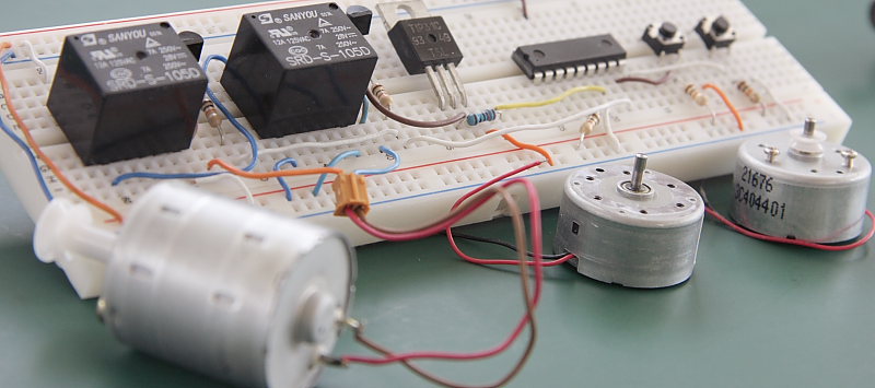
This post is about building a simple PIC16F88
Briefly about circuit operation. Press SW1 to change the motor speed by modifying output signal duty cycle thus creating variable output voltage. Press SW2 to change motor direction, see attached assembly source code for more info at the bottom of this page. Here is the design schematic, as you can see it’s relatively simple. MCU, 3 transistors and a relay will do the job. No external clock source is needed as PIC16F88
Design assembly source code is available here. See a short video demonstrating circuit operation.

