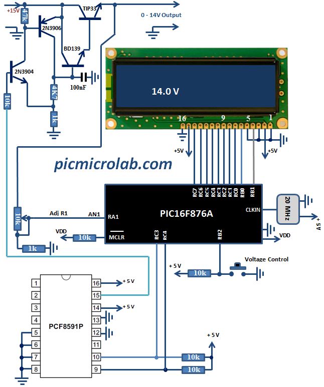
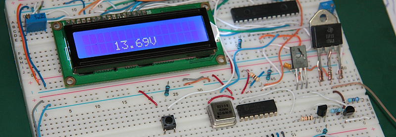
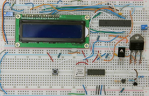
Digitally Controlled Power Supply from 0-14 Volt based on PIC16F876A will be demonstrated in this post. This is a modification of Digital Power Supply 2.5-12V article and has similar characteristics. The most noticeable difference is the use of PCF8591P I2C Digital to Analog converter instead of digital resistor controlled by PIC microcontroller. In general this configuration allows continues control of output voltage, although current software does not fully support this feature. So now let’s see how current design is supposed to work. Circuit operation is relatively simple. Push SW to increase the value sent to PCF8591P. DAC output in turn will drive TIP33 Power transistor through voltage/current amplifiers thus controlling the power supply output voltage. Output voltage is also connected to PIC16F876A ADC converter through a simple voltage divider. Digitized voltage values are shown on 2×16 LCD display. See design schematic and breadboard for additional details.

More advanced design is available at this link. You can download design assembly source code here. Meanwhile here is a short video showing circuit operation.

