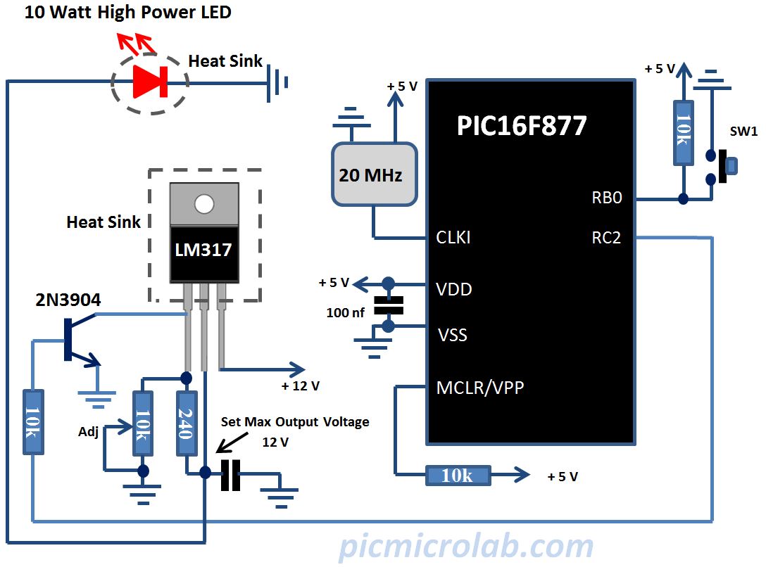
This post is about building a simple LED controller circuit. Several articles were published on this subject. Here is just one link to similar design that can be useful. Search the site for more information. Current design relies on well-known technique to control output voltage by changing its duty cycle. Pulse Width Modulation is a common way to control output voltage. Basically it’s a modified version of the code used in fading LED post. Instead of continually circling through PWM values a switch is used to increase LED brightness in preset steps. I suppose that you have a basic knowledge of PIC assembly instructions and can successfully build and download the code using a In-Circuit Debugger like PICkit 3 to your target device. In any case the source code and a precompiled HEX file are available at this link with additional comments. I always build and test all published prototypes so if you use the same components and copy the code exactly the circuit should work without any problem. Fill free to ask me additional questions through contact section at the top menu. Now a few words about hardware. Using high power LED requires additional components like LM317
voltage regulator to cope with higher current requirements. As you can see from the schematic a microcontroller PWM output is connected to the base of 2N3904 transistor
that switches the LM317
thus controlling the load.

In this particular design 10 Watt RGB LED was used. Only red LED’s were connected. Experiment with other colors or their combinations and see if you get better results. Higher power versions of this LED 20 – 50 Watt also available on Ebay. LM317
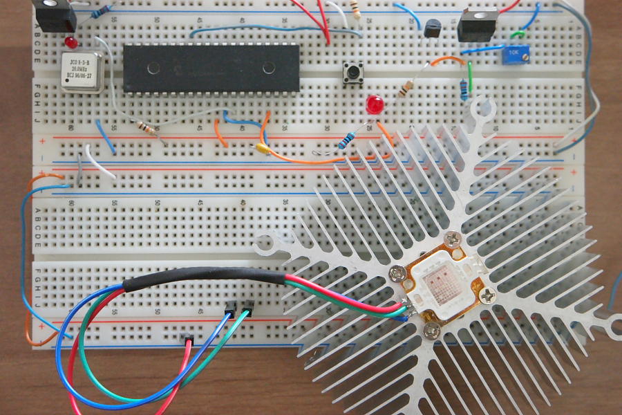
regulator and the LED should be placed on a heatsink to provide sufficient heat dissipation, they get very hot. As usual here is the prototype board with final design.

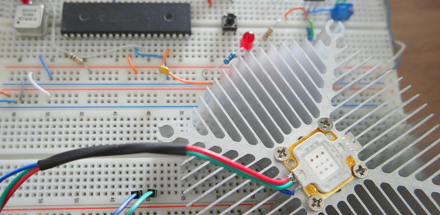
Pay attention that LED’s common positive terminal is not shown on this picture. The code was tested only on PIC16F877 controller however any similar devices with CCP modules and 10 bits resolution of PWM should work with minimal changes. More on the next page. The output voltage is controlled by pressing the SW1 switch. Existing code still needs some improvements like smoother transition of PWM values in order to achieve more gradual LED brightness changes. If you look at the short video showing circuit operation you can still see discrete changes in LED brightness.
