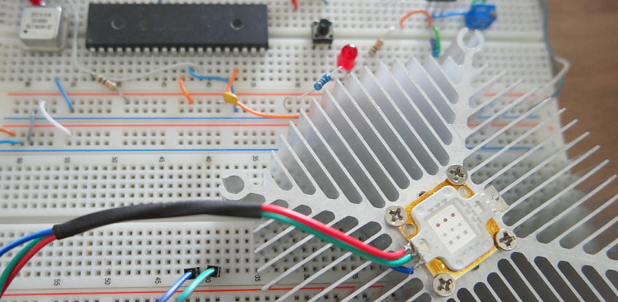
This post is about building a simple LED controller circuit. Several articles were published on this subject. Here is just one link to similar design that can be useful. Search the site for more information. Current design relies on well-known technique to control output voltage by changing its duty cycle. Pulse Width Modulation is a common way to control output voltage. Basically it’s a modified version of the code used in fading LED post. Instead of continually circling through PWM values a switch is used to increase LED brightness in preset steps. I suppose that you have a basic knowledge of PIC assembly instructions and can successfully build and download the code using a In-Circuit Debugger like PICkit 3
In this particular design 10 Watt RGB LED
Pay attention that LED’s common positive terminal is not shown on this picture. The code was tested only on PIC16F877

