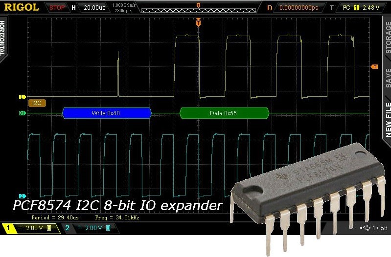
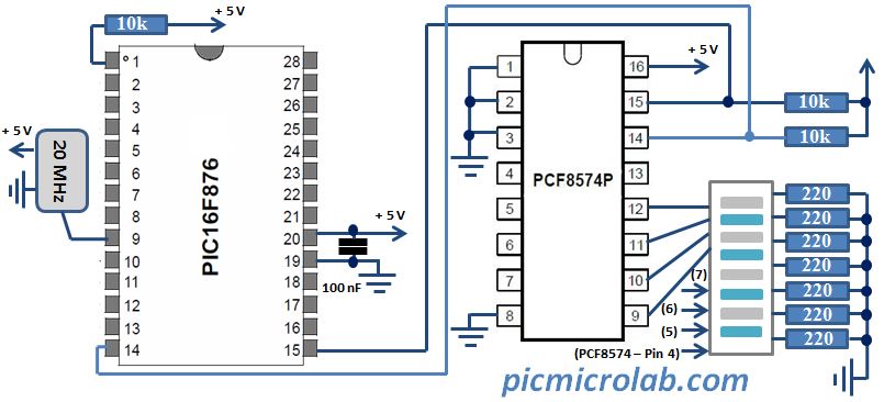
In this post we’ll review a simple interface for PCF8574 I2C 8-bit IO expander IC and PIC microcontroller. For similar Arduino based implementation click this link. The format of present post is similar to 2 recently published tutorials about I2C communication. PCF8591 I2C 8-bit A/D D/A converter and PCF8573P I2C Real Time Clock. All articles in I2C series include a basic circuit description, brief review of various modes of operation and simple code examples. Now back to PCF8574. Port expander provides a general purpose remote I/O expansion capabilities via the two-line bidirectional I2C-bus. It also has an interrupt line (INT) which can be connected to the interrupt logic of the microcontroller. This line can be useful if PCF8574 used as Input Port, however only Output code example will be shown. Full datasheet available here. PIC16F876A microcontroller was used as a master to generate clock on SCL line and send data/address on SDA line. In order to communicate with PCF8574 a valid address should be send by master followed by a data byte. In current configuration write address is 0x40 and data byte is 0x55. Read address differs only in 1 bit (LSB) that should set to “1”.So in order to read from I/O expander port you’ll need to output 0x41.I’ve also included actual screen capture of these values being transmitted by PIC. Oscilloscope screen capture was taken with RIGOL DS2072 using its I2C Decoder feature and I2C trigger mode. Attached assembly code will further demonstrate how to implement I2C communication with PIC. Design schematic and bread board picture are also provided so it can be easily followed should you decide to reconstruct or modify this circuit.


