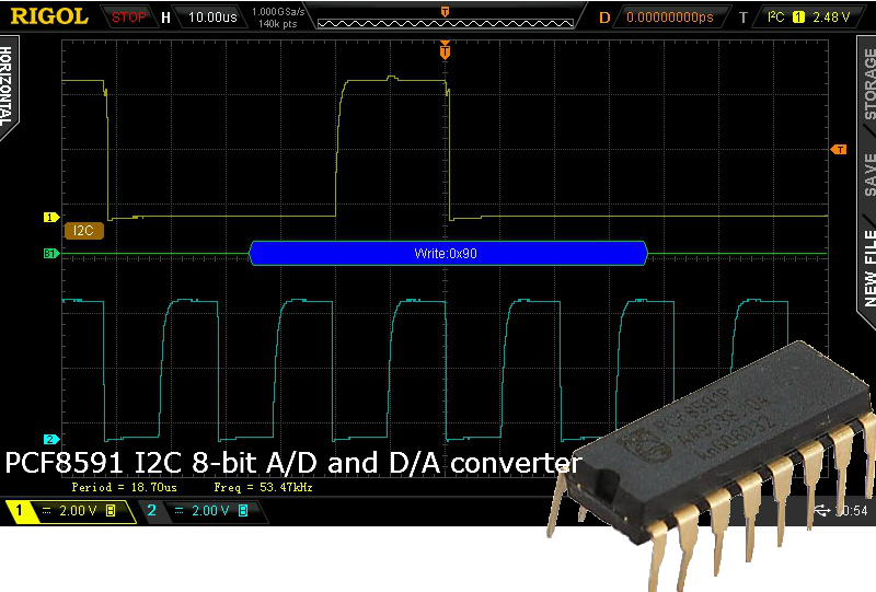
In this short tutorial we’ll learn how to control PCF8591 I2C 8-bit A/D and D/A converter with PIC microcontroller. PCF8591 was already used in a number of recently published projects like Function Generator, also I’m planning to add it to PIC Development Board design in order to extend its functionality. PCF8591 has an ADC with 4 analog inputs configurable as single ended or differential inputs and DAC with one analog output. A built in oscillator can generate the clock signal required for the A/D conversion so no external clock source is required. PCF8591 address is selected by 3 pins so eight devices can be connected to the I2C-bus. Device function can be selected by changing configuration bits in a Control register. For example sending device address, in this case 0x90 followed by 0x20 as a control byte will select AIN0 as a digital input. See full Data Sheet here. Although attached assembly code controls PCF8591 operation it can be used as a template for controlling other I2C devices, just change the address and configuration word according to device datasheet and rebuild the project. Now back to current design. Present circuit is very simple. Analog Voltage levels at the potentiometer output will be converted and displayed on LED bar graph connected to PORTB. PIC16F876A microcontroller was used however any similar PIC with I2C hardware should work.
PCF8591 I2C 8-bit A/D and D/A converter

