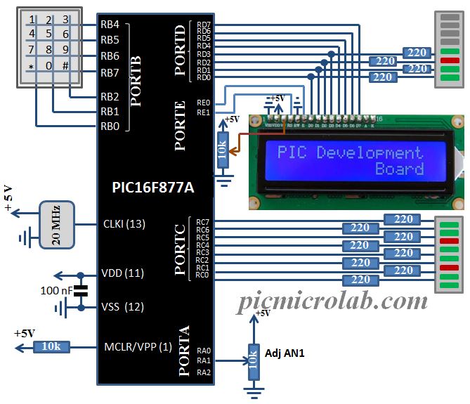
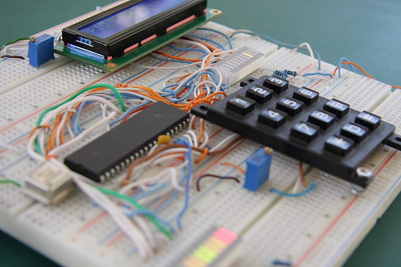
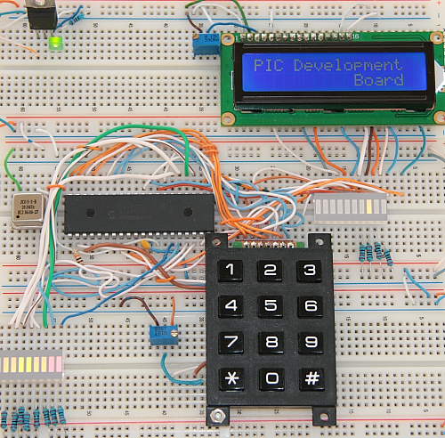
In this post I’ll show a more general approach for circuits prototyping. Instead of building each individual design to validate its operation why not to design a basic PIC16F877A based Development Board. Current design have all the necessary features of a simple board, including 10 Segment LED bar graph, 2X16 LCD Display and a 3×4 Keypad. I was planning to add some communication capabilities via I2C devices like PCF8591 A/D ,digital to analog converter and real time clock with battery backup but it will probably complicate the circuit too much. The prototype in this article was built on a standard 830 breadboard. I’ve used 3 of these boards for this purpose. Most of the projects I’ve published under PIC16F category can be tested with this board. Please explore this site for more designs that may interest you. I’ve also included a simple test program code in this post that can be downloaded at the bottom of the page. See similar design here AD9850 Signal Generator Project
The board doesn’t have a built in programming capabilities so you’ll need some sort of programmer like PICKIT2 , PICKIT3 or other compatible devices to download the code into microcontroller. Few words about the test software. Press any key to display its binary code on LED bar graph connected to PORTD. 10K Potentiometer is connected to analog channel 1, rotate it to display converted voltage values on PORTC. LCD Display data lines are also connected to PORTD and PORTE controls display Enable and RS lines. See schematic for more details. Assembly code is here.

Hope that this post was interesting and you’ve extracted some value while reading it. Much more information is available on this site. For similar projects look at PIC16F category.

